Superseded
Draft standard
Historical
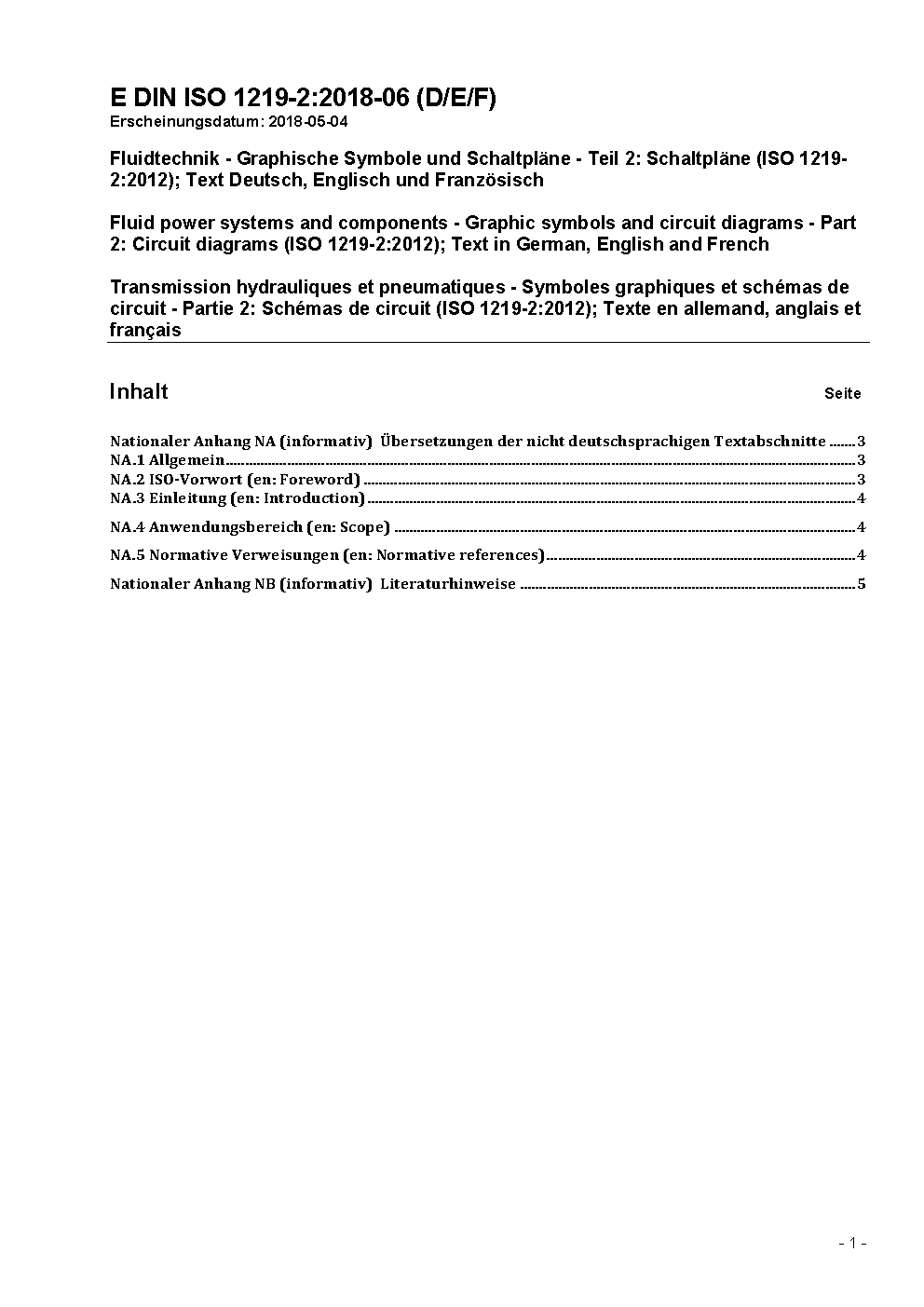
DIN ISO 1219-2:2018-06
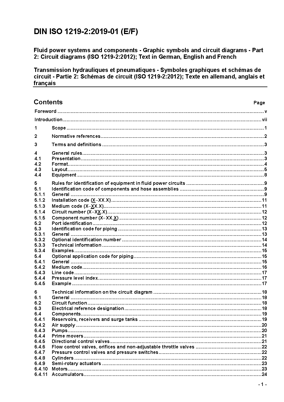
Fluid power systems and components - Graphic symbols and circuit diagrams - Part 2: Circuit diagrams (ISO 1219-2:2012); Text in German, English and French
 Preview
Summary
This part of DIN ISO 1219 series is the translation of ISO 1219-2:2015 which was developed under German project leadership by experts of the German committee NA 060-36-10 AA 'Graphische Symbole und Schaltpläne' in the department Fluid Power of the DIN-Normenausschusses Maschinenbau (NAM) and the working group ISO/TC 131/SC 1/WG 1 'Graphical symbols and circuit diagrams'. Circuit diagrams are an aid to facilitate the understanding of the design and description of installations so that, by having unified representations, confusion and error can be avoided during planning, manufacturing, installation and maintenance. This part of ISO 1219 establishes the main rules for drawing hydraulic and pneumatic circuit diagrams using graphical symbols drawn in accordance with ISO 1219-1 and also applies to circuit diagrams relating to cooling systems, lubrication systems, cooling lubricant systems and systems of technical gases used in conjunction with fluid power applications.
Notes
Prévu pour remplacer DIN ISO 1219-2 (1996-11).
Technical characteristics
| Publisher | Deutsche Institut für Normung e.V. (DIN) |
| Publication Date | 06/01/2018 |
| Cancellation Date | 01/01/2019 |
| Page Count | 56 |
| EAN | --- |
| ISBN | --- |
| Weight (in grams) | --- |
No products.
Previous versions